Matching an 11kW Inverter to a Residential Solar Power System
By hqt
2026.09.28Related Posts

C&I PV System Design: How to Plan Commercial Rooftop and Ground-Mounted Solar
October 30, 2026

What Is C&I Solar? A Guide to Commercial and Industrial Solar Systems and Examples
October 29, 2026

How to Become a SANDISOLAR Solar Distributor in Poland and Develop Your Storage Business
October 28, 2026
When it comes to a solar power system, there are two sides to electrical design: the inverter. It should be able to handle the loads it is connected to with its AC output, and the voltage and current generated by the PV array with its PV input.
Correct power rating is not the only factor to a workable system. If too few modules are used in a string, then it is possible that it will not be within the operating range of the MPPT; for too many modules, the maximum input voltage of the MPPT could be exceeded in cold weather.
Therefore, the inverter should be considered to be the interface between PV generation, battery storage and household demand.
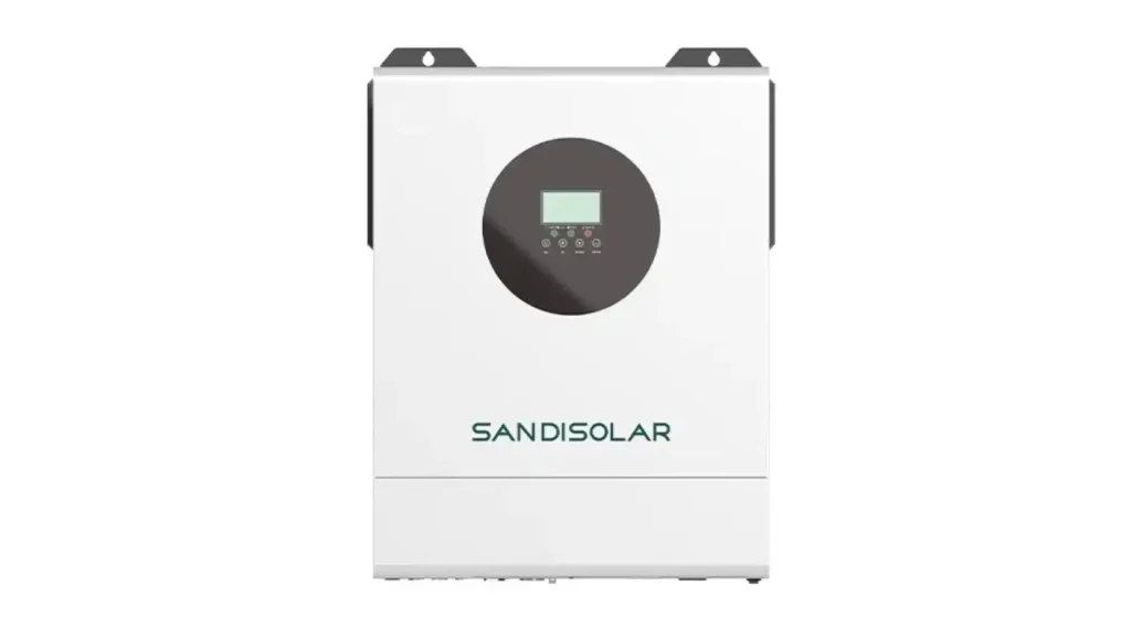
Explain the purpose of the Inverter in the system.
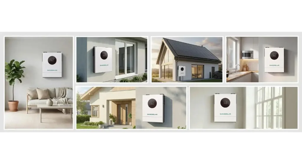
The Sandisolar 11kW model is an off-grid solar inverter with pure sine wave AC output, dual MPPT solar charging and battery charging and energy-priority control.
It can generate power from photovoltaic energy and charge the battery during the daylight hours to power the loads. If solar generation is not enough, the battery or the power from the utility can be used to power the loads depending on the set operation mode.
This is unlike the regular grid-tied inverter that, while typically used for converting power for immediate use or grid export, may not necessarily offer battery charging or off-grid backup.
The Sandisolar 11kW 48V solar inverter is designed for Residential, Remote-Site and Unstable-Grid applications.
Beginning with the Appliance Load Profile
The inverter's rated output (11KW) should be compared to the maximum simultaneous load the house has (not all loads in the house).
Classify the various appliances into continuous loads, short duration loads and motor driven loads. Lighting, communication equipment and refrigeration can run for extended periods of time and pumps, air conditioners and tools can generate short, but high, starting demand.
The load study should also be able to determine what appliances are critical during a power outage. Load prioritisation helps to minimise unnecessary battery capacity and not allow multiple high power appliances to run at the same time.
When providing output to compressors, motors, electronic power supplies or to sensitive control equipment, a pure sine wave output is important.
PV String Voltage calculation is prior to Array Power.
In addition to the total module wattage, solar-array design should start with module voltage. There are two module values which are particularly significant:
- Voc: This is an open circuit voltage in the module, which is the voltage when the module is not under current.
- Vmp: The voltage at which the maximum power is supplied.
During normal operation, the series string Vmp voltage should be in the inverter MPPT working area. The string Voc should not exceed the inverter's maximum PV input (after temperature correction).
The temperature has a direct influence on the voltage of solar-modules: the colder the modules, the higher the voltage. Even though a string may be considered safe under standard test conditions, it could be over 500Vdc in the input during cold weather.
There is thus a need to evaluate the number of modules to be connected in series at the maximum and minimum temperature likely to occur at the site.
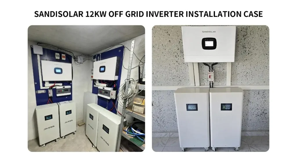
Operating under unequal solar conditions with Dual MPPT.
For Dual MPPT, two PV groups can be controlled separately. This can be helpful when modules are on roofs of varying orientations, tilt angles or shading.
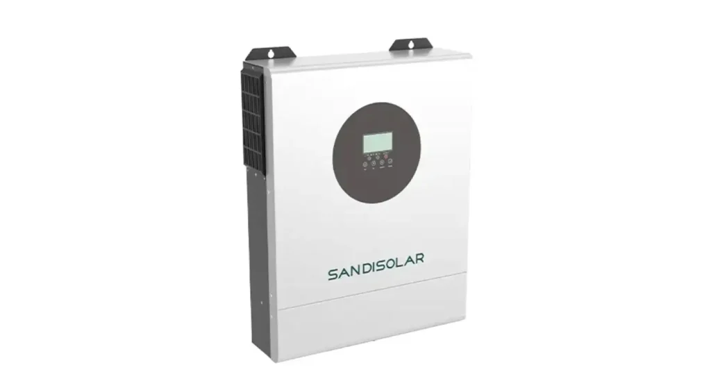
For instance, one MPPT can be used for an array facing east and the other for an array facing west. Each tracker then goes to the operating point of its array and not to one that's forced to occur at a common voltage.
All modules that are connected to the same MPPT should have similar exposure conditions and electrical characteristics. Blending unrelated module types and/or varying string lengths on a single tracker may impact the energy harvest.
The maximum PV input is 11kW, although the quantity of PV modules may have to be determined by the string voltage and input-current limits.
| Design Item | Value to Confirm | Main Risk if Incorrect |
| String Vmp | Within MPPT operating range | Weak or unstable tracking |
| Cold-weather Voc | Below 500Vdc maximum | Inverter input damage |
| String current | Within MPPT input limit | Clipping or protection trip |
| Modules per string | Equal on the same MPPT | Mismatch loss |
| Array orientation | Similar within each MPPT | Reduced energy harvest |
| Total PV power | Within system design limit | Excessive clipping |
Get to know the 160A Charging Limit
How fast solar energy can be transferred to the battery depends upon the built-in MPPT charging current. The 160A maximum rating does not indicate that the battery should be charged at 160A all of the time.
The current depends on the battery capacity, type of cell, BMS limit and ambient temperature. You might need a very low charging level for a smaller battery.
The installer should also take into account day time loads. Solar energy used for the active appliances and to charge the batteries, the charging energy varies with time of the day.
When the battery is near full, the inverter may limit PV production since there is no storage capacity to take up the power and connected loads are unable to consume all the solar power.
Correctly connect the 48V Battery
The compatibility of an inverter starts with nominal voltage, which is usually 48V for a 48V-class inverter, but the 48V-class inverter is normally used with a 51.2V LiFePO4 battery.
Check the operating-voltage range, charging voltage, maximum charge current, continuous discharge current and short duration peak current of the battery. BMS should provide the current required by the inverter without triggering any type of protection.
Means of communication should also be checked. The inverter and LiFePO4 battery communicate with each other via RS485, enabling the inverter to share state of charge, current-limit and fault data with the battery.
The LiFePO4 battery series from Sandisolar offers various voltage and capacity configurations, suitable for different types of solar storage systems.
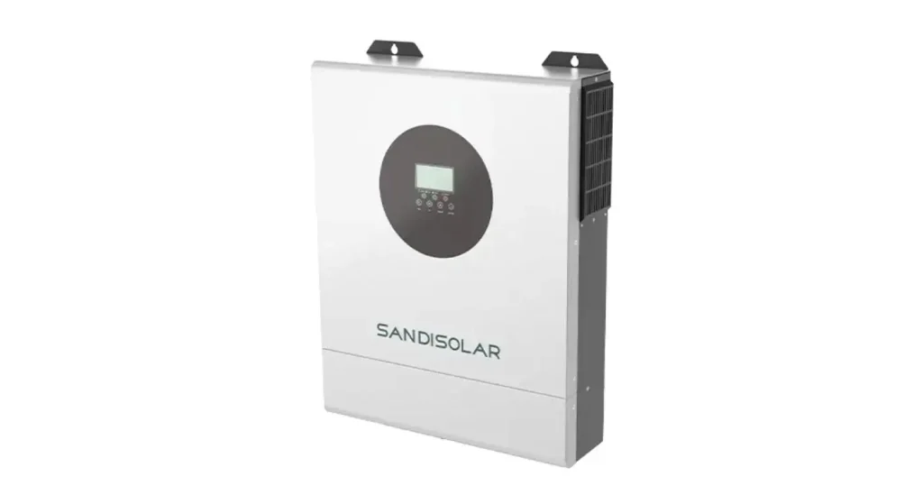
Select the proper Output Priority.
The inverter has various output-priority modes: SUB, SBU and SUF. These modes select the first power source, which can be solar, battery or utility.
Solar First can boost direct use of PV generation. The use of a battery-priority setting can decrease grid usage, but it must ensure that the amount of energy stored is sufficient to meet the needs for periods of outages. When continuous backup is more important than maximum self-consumption, a battery can be operated in a utility-supported mode to save battery capacity.
The preferred priority will vary based on the local electricity availability, tariff structure, solar availability and size of battery. The default settings should not be used instead of a specified strategy of operation.
Determine if Battery Free Operation is Feasible
When PV input and system conditions allows, the inverter can work without battery. This can help lower initial installation costs for applications primarily requiring daytime power.
But clouds, shading and time of day will affect solar power. The system, without battery, has less capacity to compensate for fast-changing generations, or to continue loading (after darkfall).
For equipment that must be powered continuously, battery-free operation is not optimal. Installation cost should not be the only consideration in deciding.
Plan Monitoring and Site Protection (2019)
Solar input, load demand, battery status and system alarms can be accessed remotely by user and installer via built-in WiFi. Monitoring data can help identify shading, circuit overloads, low charging or frequent protection trips.
The removable dust cover on the inverter may be beneficial in challenging environments, but the installation location must still be vented and a proper clearance must be maintained.
Coordination of DC isolators, fuses, breakers, surge protection and ground. Cables should be covered to prevent heat, sharp edge, moisture and mechanical damage.
To round out the solar generation and house energy management, there is a solution for residential PV by Sandisolar.
The PV Input is commissioned prior to entering into Full Operation.
Prior to stringing together, check the polarity and open circuit voltage (Voc) of each PV string. Check against the value calculated and ensure that this value is still below the inverter limit.
Test each MPPT in isolation then in conjunction for normal system operation. This allows reversed polarity, mismatching strings or unexpected shading to be easily identified.
Once the battery has been connected, check charging voltage, charging current limit, RS485 communication data and state-of-charge data. Add loads to the house one at a time and verify that the output priority that was chosen is working as desired.
You can find the manuals, configuration information etc. relevant to the Sandisolar download center.
| Inspection Area | Acceptance Focus | Verification Method |
| PV polarity | Positive and negative correctly connected | Multimeter test |
| String Voc | Matches design and remains below limit | Open-circuit measurement |
| MPPT operation | Both trackers generate normally | Monitoring-data review |
| Battery settings | Correct voltage and current limits | Inverter-menu inspection |
| RS485 communication | Correct SOC with no protocol alarm | Inverter and BMS display |
| AC output | Stable voltage under expected load | Controlled load test |
Conclusion
When it comes to choosing the right inverter for a solar power system, there's more to consider than just "inverter watts equals solar panel watts. PV string voltage, MPPT allocation, battery current, communication and load demand shall be within the same design.
In an 11kW off-grid PV installation, if the PV array is carefully calculated and the installation is properly commissioned, the chances of PV low solar yield and input over-voltage shutdowns of battery protection are minimized.
FAQs
Q1. What is the maximum number of watts of solar panels that can be installed to this inverter (11kW)?
Product can accept up to 11kW PV input. The final array should also be within the voltage and current limits of both the MPPT channels.
Q2. What is the benefit of having two MPPT trackers?
They enable the independent operation of two differently oriented/solar condition arrays. This may increase the harvest of energy over one tracker with different arrays.
Q3. What is the voltage range of the inverter for a 51.2V LiFePO4 battery?
Yes, provided that the operating voltage, charging current and discharge current as well as the communication protocol are compatible. Just the nominal voltage is insufficient.
Q4. Does it have to use a battery?
Yes, the inverter can be used without batteries. Power will still be directly dependent on the current solar generation, or the configured AC source.
Q5. Are two of these inverters allowed to be in parallel?
This particular non-parallel model does not support parallel expansion. It is recommended to choose a parallel operation design model for the project that needs to work in parallel.


Contact Us
In This Article
Related Posts
C&I PV System Design: How to Plan Commercial Rooftop and Ground-Mounted Solar
October 30, 2026
What Is C&I Solar? A Guide to Commercial and Industrial Solar Systems and Examples
October 29, 2026
How to Become a SANDISOLAR Solar Distributor in Poland and Develop Your Storage Business
October 28, 2026